NEW KF-SP (indoor key pad) Manual and data specs
You can find the manual data specs of the KF-SP Smart Fingerprint keypad below:
Original HubSpot URL: https://learn.simpled.uk/new-manual-and-data-specs-of-kf-sp
Product Overview:
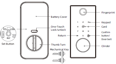
What's Included:
1x Exterior panel(Rubber pad include)
1x Interior panel
2x Keys
image-png-Jan-09-2025-04-24-03-2389-PM
1x Deadbolt Assembly & Strike Plate
1x Installation Kits
1x Mounting Plate
1x Drilling Template
1x Phone Tag (Sticker)

Screenshot 2025-01-07 at 16.24.44-1
2x Proxy Fobs
Screenshot 2025-01-07 at 16.24.54
Specifications:
Model | KF-SP |
Materials | |
Lock weight | |
Unlocking methods | Bluetooth (via the app) Password RFID Cards Mechanical key Fingerprint eKeys |
Colour | Black |
Dummy password | |
Doors applicable | |
Working voltage | Nominal voltage of 6.5V power supply with external power interface |
Door thickness | |
Data capacity | Fingerprint: 100 Password: 250 Card: 1000 |
Working temperature | -10℃-55℃ |
Working humidity | 0-95% |
Note
Note: Default admin password in initialization state: 123456 or 000 or 000000.
Operation Instruction:
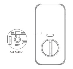
Restore factory setting Set
Press and hold the reset button on the lock
And enter“000000#"the lock will restore to
factory settings, clearing all passwords and
mobile administrators
Installation Steps: 1 in
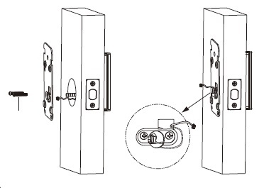
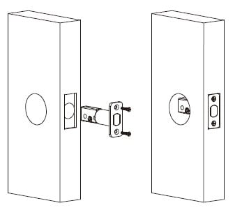
1. Install the Bolt and Strike Plate
Insert the bolt into the door.
✅ Important: Make sure the bolt is in the retracted (unlocked) position.
Install the strike plate on the door frame. Ensure the bolt will align and center properly within the strike when extended.
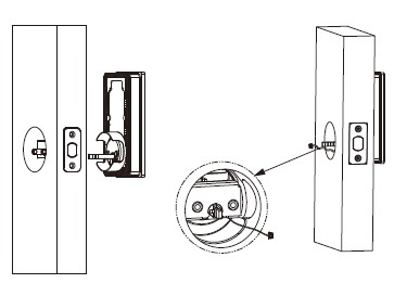
2 in
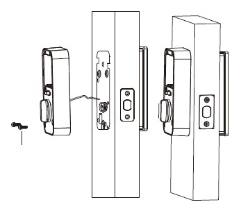
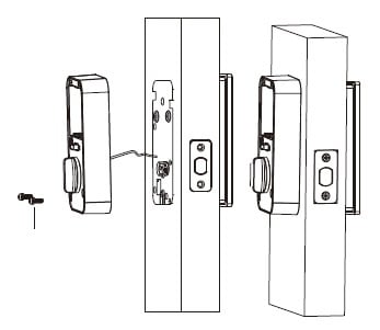
2. Install the Exterior (Outside) Assembly
Feed the cable from the exterior assembly through the door hole.
✅ Note: The cable should go below the bolt as you insert the assembly into place.
3 in
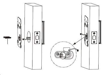
3. Attach the Mounting Plate (Interior Side)
Hold the exterior assembly flush to the door.
Route the cable through the hole in the mounting plate.
Secure the mounting plate with the provided screws.
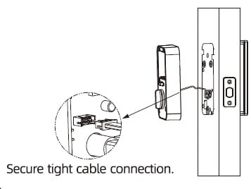
4. Connect the Cable 4 in
Connect the cable to the interior assembly’s PCB (circuit board).
🔌 Tip: Firmly press the connector in using your thumbs until it is fully seated.
5 in
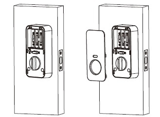
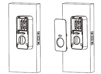
5. Attach the Interior Assembly
Place the interior assembly onto the mounting plate.
Use the included screws to secure it tightly.
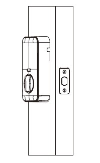
6. Test the Lock Mechanism and Door Alignment
✅ IMPORTANT: Before inserting batteries:
6 in
Test the lock manually using the thumb turn and the physical key.
The bolt should move smoothly without resistance.
If the bolt sticks or feels obstructed, double-check your installation steps for alignment.

7 in
7. Insert Batteries
Install 4 AA alkaline batteries into the battery compartment.
Replace the battery cover once done.
Your smart lock is now powered.
8 in
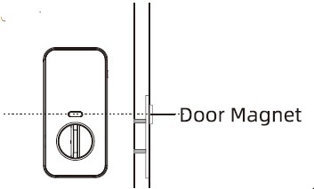
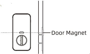
8. Setup the Built-In Door Sensor (Auto-Lock Feature)
The lock includes a built-in door sensor for auto-lock functionality.
Slide out the sensor module from the back of the interior assembly.
You may need to temporarily remove the interior assembly to access it.
Stick the magnet onto the door frame, positioned close to the sensor.
✅ You're Done!
Your Simpled KF-SP Smart Lock is now installed and ready for use.
Tip
Simpled App Installation Guide
Useful Information:
Functionality of Simpled Smart Locks Without Network Access
Rename Your Locks in the TT Lock App
Additional images from original HubSpot article

Screenshot-2025-01-07-at-16.24.44-1.png

Screenshot-2025-01-07-at-16.24.54.png
Set.jpg
1-in.jpg

2-in.jpg
3-in.jpg
4-in.jpg
5-in.jpg
6-in.jpg
7-in.jpg
8-in.jpg